A cut above: your guide to automated plate cutting
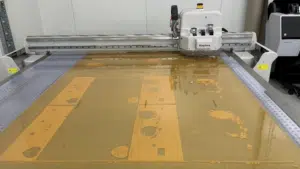
For more flexo packaging prepress departments, automated plate cutting tables have moved from being ‘nice-to-have-but-not-essential’ to a smart investment in the production process. Steve Smith explains the benefits of cutting tables and how the latest developments in Miraclon’s TAP plate layout software further enhance prepress and pressroom efficiencies.
Why invest in automated plate cutting?
To appreciate the benefits of cutting tables, consider how time-consuming and complicated it is to cut plates manually. It’s not uncommon for one plate layout to carry as many as 20 separations with different repeats. Manually cutting these out of the layout takes time and the task becomes more complicated when repeats are staggered on the plate (by 30mm or so) to mitigate “bounce” on press.
Additionally, press operators should not have to further cut the plate to fit the sleeve, because this risks damaging the sleeve – or, even worse, cutting fingers. In any event, the use of scalpel-like blades is now banned from many print rooms for safety reasons. It’s important that plates leave the prepress department cut to the precise dimension needed for the job. This saves time in the plate-mounting area.
Cutting practice makes identification easier
As well as being faster, more accurate and safer, using a plate cutting table can also help press operators identify separations more easily when assembling sets. This is because the cutting table “best practice” is to cut the plates face down (i.e., with the back of the plate facing up). Cutting face-up often leaves a burr on the film base of the plate, which procedures a poor seal between the plate and the double-sided mounting tape. This can also lead to what is known as “plate join TEV” on press, where the burr creates a “lip” on the plate edge.

If you’re wondering how this helps with easier identification, the cutting table software delivers data from the file to the cutting table, which can automatically annotate the back of the plate with details such as job name, separation and the DIGICAP NX Patterning settings applied using the pen tool on the cutting table. Given that the six colors in a set could be on six different layouts, this is a big time-saver and keeps you organized.
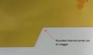
Cuttings tables also reduce the risk of tearing the plates when demounting in cases where there is an internal corner. Tearing often occurs when the separations are staggered. Manual plate-cutting usually ends up with a cut overlap in the corner, weakening the corner and making it susceptible to tearing when demounting the plate. The cutting table can reduce this risk by cutting these corners with a rounded cut.

New seamless workflow to utilize cut shaptes generated in third party workflows
For some time now we have been able to drive cutting tables (principally the popular Kongsberg and Zund tables) using files from KODAK TIFF Assembler Plus (TAP) software plate layouts to automatically cut all plates on a single layout.
The initial workflow we developed required manually creating a solid separation layer to define the cut shape for the stepped file. The shape is added to the PDF of the stepped file and ripped. The resulting separation, typically named “cutline” or “cut shape”, is then applied to the print separation as a “mask” when adding this to the layout in TAP. The software creates a file that is sent to the cutting table and the knife follows the edge of the shape.

Creating the mask this way typically requires manual intervention to create the mask shape and then remove all external elements that are on the same separation layer such as registration marks, file name, etc., before being able to apply the mask to the separation in TAP.
Miraclon has now developed a workflow that takes the cut shape data generated in popular third-party print-ready layout solutions, eliminating the need for the manual creation of the solid separations to be used as the cut shape. This streamlines and automates the entire cut shape process, saving on average 20 minutes per job.
The new workflow uses the cut shape data from LEN files generated in third-party workflow solutions. With TAP converting the LEN files into the standard TIFF files used in TAP, any cut shapes embedded in the LEN files are automatically carried across into the TIFF file and are displayed as an “embedded mask” in TAP. This workflow is convenient when there is more than one cut shape for a single job. This is often the case when trying to reduce the effect of the plate join or when an eye mark falls across the standard plate join, requiring the colors that make up the eye mark to be cut differently.
Utilizing a commercially available print-ready layout software, you can create plate cut shapes. If one common plate cut shape is required to be used across all the separations in a job, only one cut shape is created, which is embedded in each separation. Where there are more than one – it only needs to be more than one – each separation will have an individual cut shape assigned.

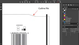
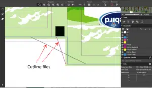
With this workflow, cut shapes are automatically generated as a 0.25mm keyline outline of the cutter shape as a technical link within the separations. These keylines can be displayed in online review and approval tools to show the position of the cut shapes. These keylines can also be used when saving the stepped file as a PDF to be sent to any RIP, by turning off the technical ink selection, making them a separation to be used by TAP as a mask. This removes all manual tasks of creating cutter shapes.
TAP can either work with embedded cut shapes in the LEN files or by applying the ripped mask cutline separations as an external mask (cut shape). If applying an external mask, the operator must locate the cut shape created for the separation. Using the embedded mask eliminates the need for this selection and reduces the risk of selecting the wrong file.
Using cut shapes (masks) crops the separation to be imaged to the cut shape. There is typically more area around a separation than is required on the plate. Unless this is trimmed off, the plate will be imaged to a larger area than necessary – reducing the number of plates that can be placed on one layout. This is extremely valuable when a separation consists of multiple steps (repeats) of the same pack across a plate. If you seek to reduce “bounce” on press, these repeats are often staggered on the plate by stepping each repeat to be 30mm or so in a stagger across the plate. The resulting file is “seen” by TAP as a rectangle. Applying a cut shape to these files allows the plate to be laid out in TAP where other plates can be placed, or “nested”, in the void of the stagger*, improving plate utilization or reducing waste. This can be used even if there is not a cutting table available, as it improved plate utilization.
*This requires the TAP preference allowing overlapping elements.
Helping gravure-to-flexo transitions
The new workflow also aids in the conversion of flexible packaging from gravure to flexo by simplifying the job to minimizing the visual effect of the plate join gaps or the position of the plate join, which is usually accomplished through complex cut shapes. Third-party software can assist with creating an accurate plate join, which can be any shape and could even “weave” through a design. Automatically creating the cutter shape with the new workflow enables complex cut shapes to be defined and created cost effectively. The accuracy and speed of automated cutting provides results that could never have been achieved with manual cutting.
Steve says:
 To fully appreciate the benefits of cutting tables, just think how time-consuming and complicated it is to cut plates manually. It’s not uncommon for one plate layout to carry as many as 20 separations with different repeats. Manually cutting these out of the layout takes time and the task becomes more complicated when repeats are staggered on the plate (by 30mm or so) to mitigate ‘bounce’ on press.
So why invest in automated plate cutting? As well as being faster, more accurate and safer, using a plate cutting table can also help press operators easily identify separations when assembling sets.